The hit sink became very hot to the touch. Worrisome. Especially with some of the extremely hot weather we get in Toronto during the summer months. Converting so much of my bike's electricity into waste heat also seemed like.. a waste.
So I decided to see if there were any more efficient ways to convert 12vdc to 5vdc and I came across the LM2675 High Efficiency 1A Step-Down Voltage Regulator. This seemed much more suitable so I ordered a bunch from an online parts source, since there were no local shops that carried it. I had to buy 5 units, but I may want to build another some day, so that doesn't seem like a bad deal.

I assembled a new power supply using one of the reference circuit diagrams from the LM2675's documentation.

A couple of capacitors, a diode, an inductor and the LM2675 IC.


Quite the size difference, eh? >.<

But everything ran nice and cool once it was put together. Even pulling enough watts to run both cameras from the one IC, rather than from three 7805 ICs the way my previous design did.
I assembled everything into a new project box, adding a power socket as well so I could easily take the power supply off of my bike for things like winter storage. I don't want to leave those capacitors sitting out in zero degree weather for extended periods. Might not bother them, but better safe than slurry. I decided to leave out the heated grips switch this time.. didn't really ride much in cold weather last year. *shrug*

Another burn in test...
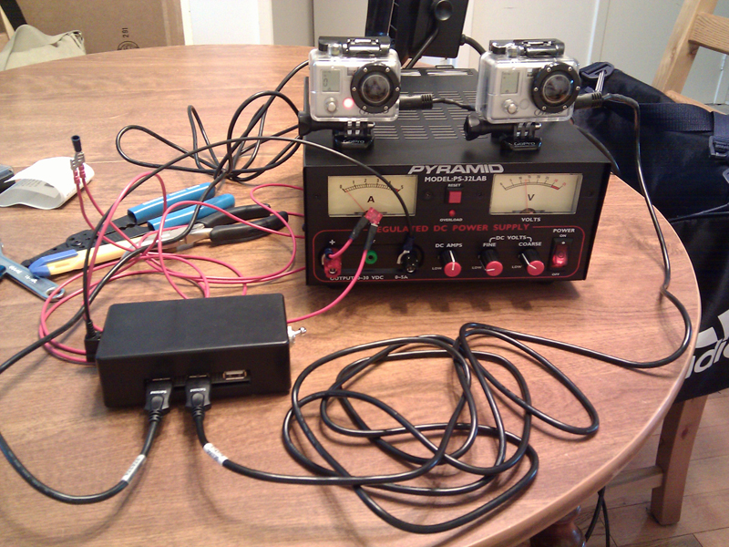
Which barely drew any current from the power supply that I used as a stand-in for the bike battery. That red thing is a bodged in 10 amp fuse for just in case something shorts.

And I was all ready to install the power supply and USB cables in my bike.
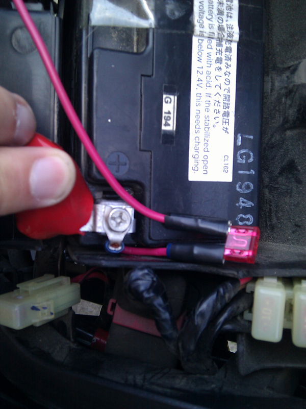

I bought these great stick-on tie downs from Sayal, which made it a breeze to zip-tie the wiring into place in the bike. They should be easy to remove if/when I want to remove the power supply.. always something I like to keep in mind when building a mod: How easily can I un-do this and take it back to stock?

The power supply will ride, loose, inside the storage area under the passenger seat on my bike. It's so cool now that I don't need to have it out in the open so keeping it somewhere that stays dry makes it much easier to build the project box.

Nose camera: Check!

Tail camera: Check!

Ready to go shoot some video. (That's my old Ruckus in the background. Sold it this spring.)
So here's a view from the tail of my bike, going for a short blast on the 401. ^_^
That's it for building a power supply for my Honda. Please leave a comment to let me know what you think or to ask me questions if there's anything you want more detail on.
No comments:
Post a Comment