2011-03-26

Megumi's PC - Build Part 3

I found that the Pyramid PS32LAB Power Supply just couldn't supply enough amps to run the computer, so I purchased a standard ATX computer power supply and built a socket that allowed me use it as a power supply for Megumi's PC.

Here's the socket.  I built it by scavenging a socket off of an old, broken motherboard, and then jumped the Power On and Power OK pins, as shown, to force the power supply to switch on when it's power switch is turned on.  Normally it requires a "power on" signal from the mobo to switch on and a "power is ok" signal to stay on, otherwise it just shuts off again.


Then I added wire tie posts for Ground (COM), +12VDC and +5VDC.  There's also +3.3VDC but I haven't added a post for it yet.  I plan to mount the socket and posts into a project box, so it will be available whenever I need to get power of of an ATX power supply.


After doing some test with a multimeter to make sure the voltages were all correct, I hooked the computer up...


...and gave it a test boot.  Nothing.  Bugger. :(  I noticed the mobo has a "memory fault" LED that was lighting up, so after some experimenting I found that it will only boot with a single stick of memory in.  I'm not sure why but I'll try and debug it.

Important thing is that it does boot and I've installed WinXP and the mobo drivers.


Next step will be getting some web cam recording software installed and testing it out as an automatic recording platform.

ATX Power Supply Modding

This post is details, for my own reference, on how to mod an ATX power supply so that it can be used as a source for 12VDC and 5VDC.


To turn on an ATX power supply that isn't connected to a motherboard use a wire or paper clip to short the green wire (pin 14, PS_ON) to any one of the black wires (COM).

The power supply shuts down if it doesn't receive a power good signal within about 3 secs. You need to short "Power OK", pin 8 on the diagram to a +5v line to keep the P/S operating.


The following is from Wikipedia.

ATX 2.0 Connector

24-pin ATX12V 2.x power supply connector (20-pin omits the last four: 11, 12, 23 and 24)
ColorSignalPinPinSignalColor
Orange+3.3 V113+3.3 VOrange
+3.3 V senseBrown
Orange+3.3 V214−12 VBlue
BlackGround315GroundBlack
Red+5 V416Power onGreen
BlackGround517GroundBlack
Red+5 V618GroundBlack
BlackGround719GroundBlack
GreyPower good820ReservedN/C
Purple+5 V standby921+5 VRed
Yellow+12 V1022+5 VRed
Yellow+12 V1123+5 VRed
Orange+3.3 V1224GroundBlack
  • Pins 8, 13, and 16 (shaded) are control signals, not power:
    • "Power On" is pulled up to +5V by the PSU, and must be driven low to turn on the PSU.
    • "Power good" is low when other outputs have not yet reached, or are about to leave, correct voltages.
    • The "+3.3 V sense" line is for remote sensing.[7]
  • Pin 20 (formerly −5V, white wire) is absent in current power supplies; it was optional in ATX and ATX12V ver. 1.2, and deleted as of ver. 1.3.
  • The right-hand pins are numbered 11–20 in the 20-pin version.

Four wires have special functions:
  • PS_ON# or "Power On" is a signal from the motherboard to the power supply. When the line is connected to GND (by the motherboard), the power supply turns on. It is internally pulled up to +5 V inside the power supply.[8][9]
  • PWR_OK or "Power Good" is an output from the power supply that indicates that its output has stabilized and is ready for use. It remains low for a brief time (100–500 ms) after the PS_ON# signal is pulled low.[10]
  • +5 VSB or "+5 V standby" supplies power even when the rest of the supply lines are off. This can be used to power the circuitry that controls the Power On signal.
  • +3.3 V sense should be connected to the +3.3 V on the motherboard or its power connector. This connection allows for remote sensing of the voltage drop in the power supply wiring.

2011-03-12

Megumi's PC - Build Part 2

A day driving around buying bits & pieces, followed by an evening of soldering and building cables, and it's more-or-less wired up.


  • removed the 2 pin connector for the power LED and soldered the wire to the board
  • made longer 3 pin cable to connect the mobo's case fan to the fan-in on the accessory panel
  • made a 4-pin 12v Molex cable out of two scavenged from old power supplies
All that's left, I hope, is hooking up the hard drive and building a power harness for booting it up.  While at Sayal I gave in to temptation and bought a Pyramid PS32LAB Power Supply for all my DC voltage power supply needs.  No more hunting through a drawer full of orphaned wall warts to try and find something with a voltage and amperage that matches the current project's needs. :)

2011-03-11

Megumi's PC - Build Part 1

I've purchased all of the hardware for Megumi's PC and have started putting it together.. but there have been a few issues...

On Monday I picked up the computer case, additional bracket and 4 pin power cable from ITX Canada, a nondescript door on the back side of a concrete block building in a business park in Markham.  ITX Can. is more of a parts warehouse rather than a full-on computer store, where they ship parts rather than deal with walk-in customers.

Unfortunately they gave me the wrong 4 pin cable, and even more unfortunately I didn't realize it until after I'd gotten home.  Turned out that they didn't even have the correct cable in stock. *sigh*  No biggie, it happens, many companies have a hard time keeping their website's stock tracking up-to-date, but now I need to make my own 4 pin cable.  Luckily I have several old computer power supplies I can scavenge for parts to make my own. :)

On Wednesday the courier tried to deliver the rest of the components and, of course, no one was home, so on Thursday I drove to their head office after work (in a driving slush storm) to pick them up.  From now on I have to remember to get packages courier'd to my work address, as there's never anyone home now that Colby has found a job.

Once I got everything home I quickly realized that there was no way to fit the mobo and power supply into the case I'd bought.  Augh! So this evening after work I had to make another trip back to ITX Can. to return the first case and pick up a Mini Box VoomPC 2 Mini ITX Case instead.  About twice the price, and good gods but it's heavy!  But everything fits, here are the components attached to the case's base plate:  The case's accessory board (USB, power LED & stereo output), the power supply and the mobo.


But I've run into two problems with the cables supplied with the case.

The cable to connect the front panel USB on the accessory board to the mobo is far too wide.  It overlaps the pins next to it for connecting the case's power LED to the mobo (or power supply).


Hopefully you can see what I mean in the photo.  This is just a poor cable choice on Mini Box's part, they should have supplied a slimmer square cable and not this chunky thing.  I'll have to go looking for a replacement.. or forgo having a power LED.  That might work too as I dislike devices that have LEDs glowing away on them all the time, eating up power while being ignored 99.9% of the time.

Then I found that the cable for connecting the mobo's Case Fan to the Case Fan-In on the accessory board is about five centimeters too short.


Another screw up by Mini Box.  They should have provided a cable that can reach anywhere within the area that a Mini ATX mobo fills, not something that only works with specific mobos.

Other than these two very poor cable choices it seems like a good case, there aren't many other choices, and the helpful staff at ITX Can. will probably lynch me if I try to return this one too. ;)

I'll have to make trips to Canada Computers and Sayal to buy better cables and/or the components to make my own.

2011-03-06

Megumi's PC - Hardware

I've started building an in-car computer for Megumi, my smart Fortwo.  Just want to keep a record here of how it goes together, for future reference and in case it might be helpful for anyone else considering the same thing.

Reason
So why am I building a car PC?  Mostly to act as kind of a "black box" device, to record what happens to my car while I'm driving it.  I have been using two GoPro cameras on Megumi's nose and tail to record video when I'm doing my daily work transit.  I was using these cameras on my motorcycle, "Arthur", a Honda CBR125, and I"ll be transferring them back onto the bike once riding season starts.

I'd also like to have the OBD data tracked in Megumi while I'm driving.  I have an OBDLink Bluetooth device which I've used in the past to connect to my Android Nexus One phone to view the car's data while driving, and I'd like to use it as part of the black box system to track this data as well.  I'm not certain how useful it'll be but you never know...

As you may have guessed, I'm a bit of a technophile. :)

Hardware
After doing a few days of research I've ordered some computer hardware from two online stores; Newegg and ITX Canada.

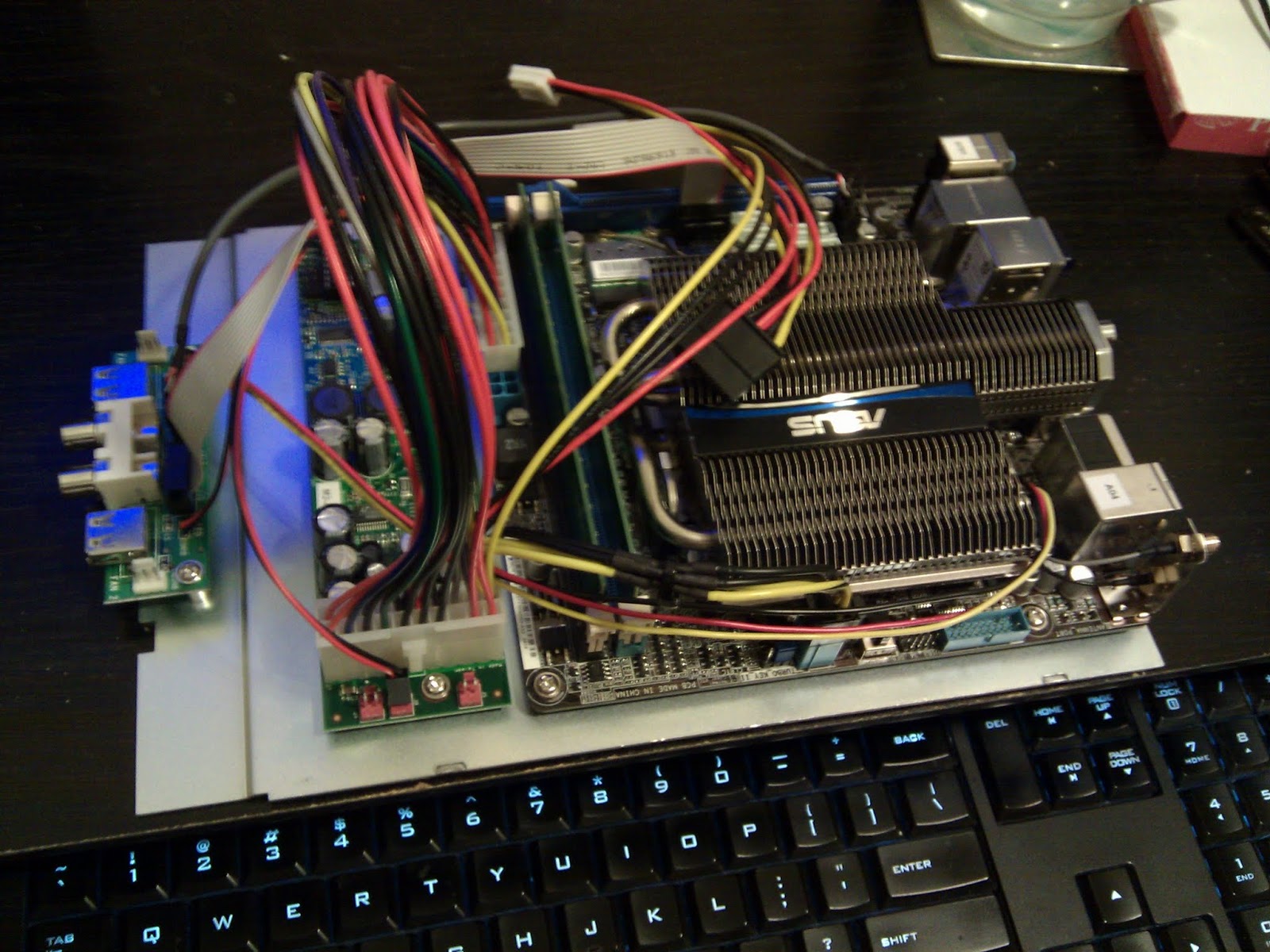
Motherboard, CPU, GPU
ASUS E35M1-I DELUXE AMD Zacate E-350 AMD Hudson M1 Mini ITX Motherboard/CPU Combo
I settled on this mobo/cpu after reading through the reviews of a dozen or so other similar boards.  Initially I thought I might get a mobo that required a seperate CPU, but as machine is going to be living in an environment with a lot of vibration and frequent jolts, a CPU that's soldered to the mobo makes more sense.

This mobo also has Bluetooth connectivity built right into it, so it should be a snap to hook it up with my OBD Link reader and give the car PC access to the Engine Control Unit's data stream:  Speed, fuel efficiency, throttle position, etc.

Memory
Crucial 4GB (2 x 2GB) 240-Pin DDR3 SDRAM DDR3 1066 (PC3 8500) Dual Channel Kit Desktop Memory
Not really a critical component, so long as it's reasonably fast memory that will work with with the mobo.  I'm only going to be running WinXP and no really intensive apps - no 3D gaming while I'm driving - so it doesn't need gobs of memory.

Hard Drive
Patriot Inferno PI60GS25SSDR 2.5" 60GB SATA II MLC Internal Solid State Drive
The hard drive however is important.  I plan to record video to it, so it will have to be reasonable sized, fast and very shock resistant.  An SSD is the best choice.  It's relatively expensive, but it should run problem free.

Power Supply
M2-ATX-HV 140w Intelligent Car PC DC-DC Power Converter
Designed to wire into the car's battery and ignition this should switch the PC on and off all on it's own.  Hopefully it won't be too big a draw for my Fortwo's little battery.  It's one thing that's a mystery to me; exactly how much power this set up with draw and if Megumi can handle it.  I'm pretty certain it won't be a problem but... *fingers crossed*

P4-12V to P4-12V 4-pin Power Cable
Required to connect the power supply to the mobo.

Case
Mini Box M350 Embedded Fanless Mini-ITX Case
Mostly just a box to hold it all.  This will probably end up stuck to the floor behind the driver's seat, or perhaps under one of the seats, depending where it fits.  I'd prefer to have it out of sight and out of direct sunlight.  I also ordered an add-in bracket which will allow me to mount fans, if needed, though the case and mobo are both fan-less so it should be a very quiet system.

The one thing I haven't bought yet is the cameras as I need to do a bit more research to find cameras that will work best in the car's environment.  I do have one or two around here, somewhere, that I can use for testing as I set up the PC and software.  The plan is to build a "headless" system that doesn't have a mouse, keyboard or monitor, that just boots up and starts recording when the car starts.

But with the flexibility and expandability of a standard PC I should be able to add hardware and software to it as my requirements evolve; perhaps adding a small touch screen, GPS receiver, connecting it's audio output to Megumi's stereo, that kind of thing.

2011-01-29

Makerbot's Deluxe Filament Spindle & Box MK1 Kit

I bought the spindle and box kit along with 5 lbs. of black plastic, and boy is it.. well.. not exactly 'crap' but certainly in need of improvement.  For $100 I was expecting more.

Assembling it was quite tricky, and I accidentally split some of the fragile plywood where the teeth from  one side socket into the holes in another.  If anyone else is building one of these I recommend that you spend some time sanding down the teeth so that the fit more easily.

The free spinning spindle was an issue while I was doing some test prints, trying to get my Skeinforge settings dialed in.  The plastic went underneath and snagged on the axle hardware.  There's no way to keep it from going underneath, and if you want to back the spindle up there's only a tiny hole at the very back that you have to try and wedge your fingers into to turn the spindle a few degrees at a time.  Madness!

So I've made a few modifications...


I cut small squares out of an old foam camping mattress pad and stuck them to the bottom of the spindle with double sided tape.  Then I used washers on the bolts that hold the spindle in the box to adjust how much they were pressing into the bottom of the box, so that the spindle could still rotate fairly easily but not just freewheel the way it had been.  Hopefully the foam can help keep the plastic out from under as well.

I also remove the front plastic face plate, to make it much, much easier to rotate the spindle backwards.  The plastic isn't quite as well protected from dust and such, but so far that has never been a big issue for me.. certainly not as big an issue as not being able to rotate the spindle.

Now I can get back to dialing in my Skeinforge settings.